
Placement, Filtering, Masks, and Object Detection
PRISM samples the receiver mesh, selects an eligible source, resolves its size/rotation/offset, and then applies the active placement rules. A useful tuning order is: make an unmasked result at the right density and scale; add spacing and face rules; add one filter at a time; use Preview Placement to check the final result.
Placement masks
Section titled “Placement masks”Enable Placement Mask in Filtering to limit where placement is allowed. The global mask applies to entries that do not override it. A source can enable Override Placement Mask in its Filtering tab for a different local rule.
Mask Cutoff controls the value at which a mask accepts a location. Invert Mask reverses the result where available. Mask Validation has two modes:
Center Pointchecks the resolved placement center. It is the default and fastest choice.Footprintchecks the resolved center, corners, and edge midpoints after size, rotation, planar offset, and face fitting. It is stricter and slower, and helps prevent a large detail from extending beyond a masked area.
Mask patterns
Section titled “Mask patterns”| Pattern | When to use it |
|---|---|
Material Base Map |
Place in bright or dark areas of the receiver material’s base map. |
Radial Center / Radial Edge |
Concentrate detail in or around a circular area. |
Corners |
Add wear or detail near object-space corners. |
Horizontal Band / Vertical Band |
Limit placement to a horizontal or vertical object-space strip. |
Edge Frame |
Add detail around an object’s object-space outer frame. |
Noise Patches |
Create procedural, visible islands of allowed/blocked placement. |
Under Anchor / Drip Streaks |
Generate directed streak placement beneath assigned anchors. |
Custom Texture |
Use a readable texture mask sampled from mesh UV0. |
Custom |
Expose the underlying source choices for specialized setups. |
Object-space masks use Object Plane to choose their working plane; Auto From Normal is useful when the sampled receiver changes direction. Procedural masks show a swatch where available, and Preview Mask is the best way to tune their cutoff and falloff.
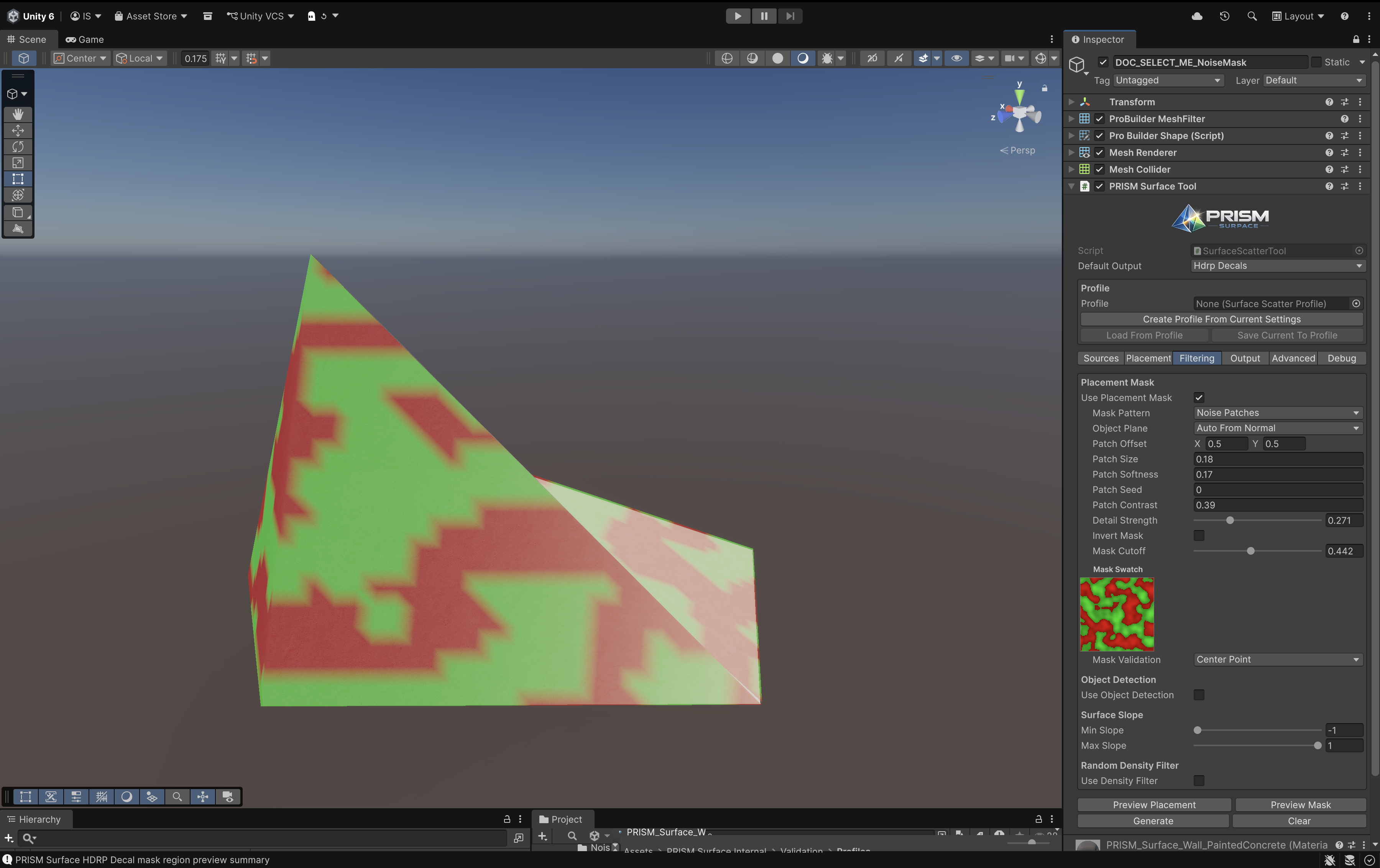
Noise Patches in Preview Mask, with the matching Filtering controls visible.
Material Base Map masks
Section titled “Material Base Map masks”Material Base Map samples the receiver renderer’s base texture. Use Texture Mapping / sampling mode Auto for PRISM triplanar materials, or choose UV0, Triplanar Object, or Triplanar World explicitly when needed. Read From selects Luminance, Red, Green, Blue, or Alpha; Place On chooses Bright Parts or Dark Parts.
The selected base map must be a readable Texture2D. If the result seems different from the visible material, check the receiver material, mapping mode, selected channel, Bright/Dark choice, and Mask Cutoff before changing other placement rules.
Object Detection
Section titled “Object Detection”Object Detection uses assigned targets to either keep scatter away from a region or place it around one. It can be global or per entry.
Avoidrejects Mesh Quad footprints or HDRP Decal projection volumes that touch a target shape plusAvoidance Range.Place Aroundaccepts output in the band betweenNear RangeandFar Range. The full footprint must clear Near Range, while at least part must remain within Far Range.
Available target shapes are Object Bounds, Circle, Ellipse, and Rectangle. Object Bounds combines enabled child Renderer and Collider bounds. The other shapes use the target Transform and project into the sampled receiver plane; an empty helper object is useful for a clean anchor. Ellipse and Rectangle expose Width / Length and Shape Rotation.
A per-entry Place Around source gets a dedicated placement pass, so unrelated entries do not consume its candidate attempts. Give it Override Density when the band needs a distinct attempt budget and Override Soft Limit when it needs a maximum count.
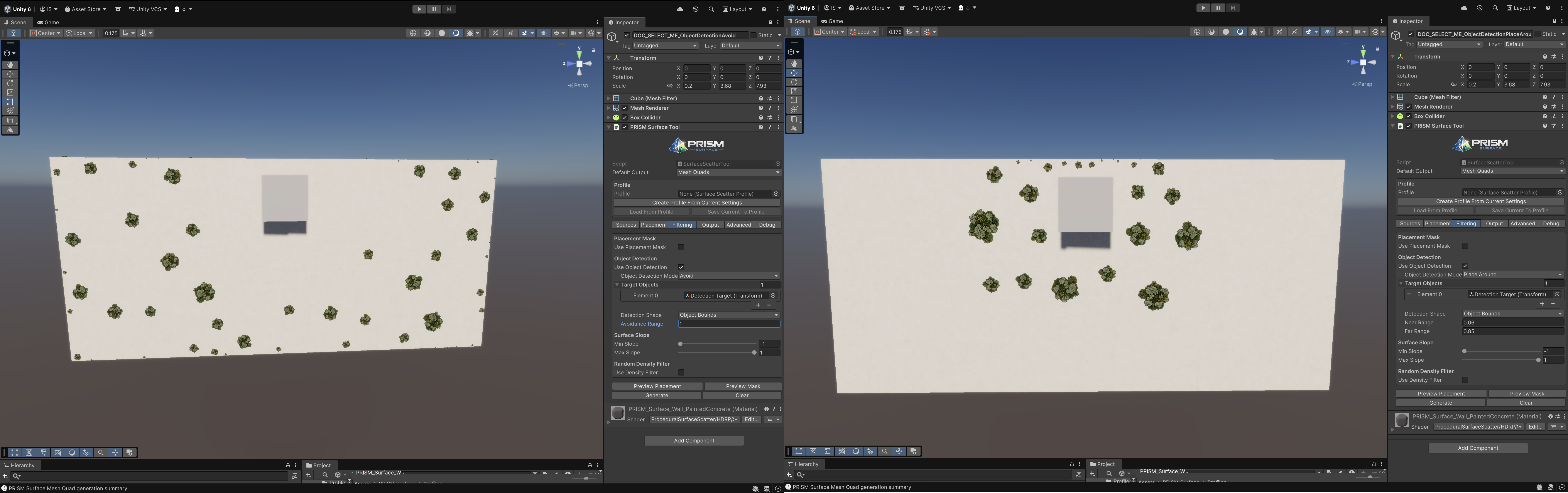
Avoid leaves the target clear; Place Around fills the configured Near/Far region.
Under Anchor / Drip Streaks
Section titled “Under Anchor / Drip Streaks”Choose Under Anchor / Drip Streaks when a stain-like source should originate below one or more anchor transforms. Assign Anchors, then choose Placement Mode:
Edge Guideddistributes streak slots along an anchor’s lower edge. It is the practical starting mode for leaks and grime drips.Random Areauses the wider stain-shaping controls for a less edge-specific region.
For Edge Guided, start with Streak Count, Coverage, and Fit Width To Edge. Add Width Variation, Streak Length Variation, Top Gap, Random Mirror X, and Horizontal Jitter only after the basic distribution works. Allow Overflow deliberately lets a streak extend beyond the clipped anchor edge. Use Use Alpha Bounds For Alignment when the artwork has transparent padding and you need its visible top edge to align; this requires a readable source texture.
Advanced Drip Controls contains bounds, candidate, downward jitter, and validation settings. Use Advanced Drip Mask Validation checks edge-guided candidates against anchor depth and surface-normal tolerances; enable it only when the straightforward setup needs extra rejection control. Use Preview Placement and the optional anchor-drip diagnostics to understand why streaks are accepted or rejected.
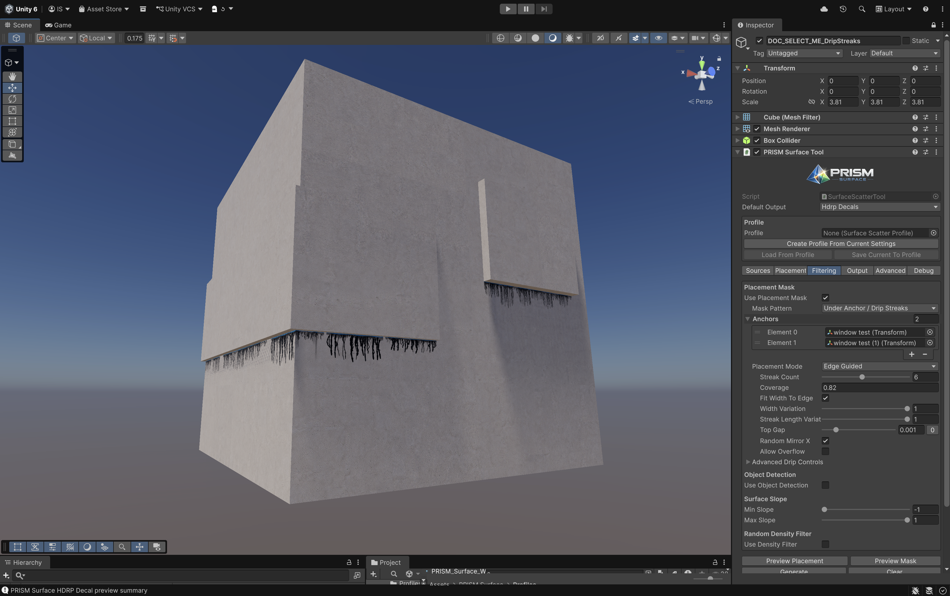
Edge Guided drips attach beneath the selected anchor edges.